Coffeenator
📁 Source code: View on GitHub →
Like many other humans, I like need coffee. I’m not especially fancy about my coffee… I just… like need it. I always got frustrated by the daily routine of filling up the coffee pot and dumping it in the tank. The minor annoyance got me thinking: How can I overengineer a solution to this problem?
The answer was simple. Run a water line to the tank and make an electronic way to control the flow of water into the tank. The solution boils down to the following components:
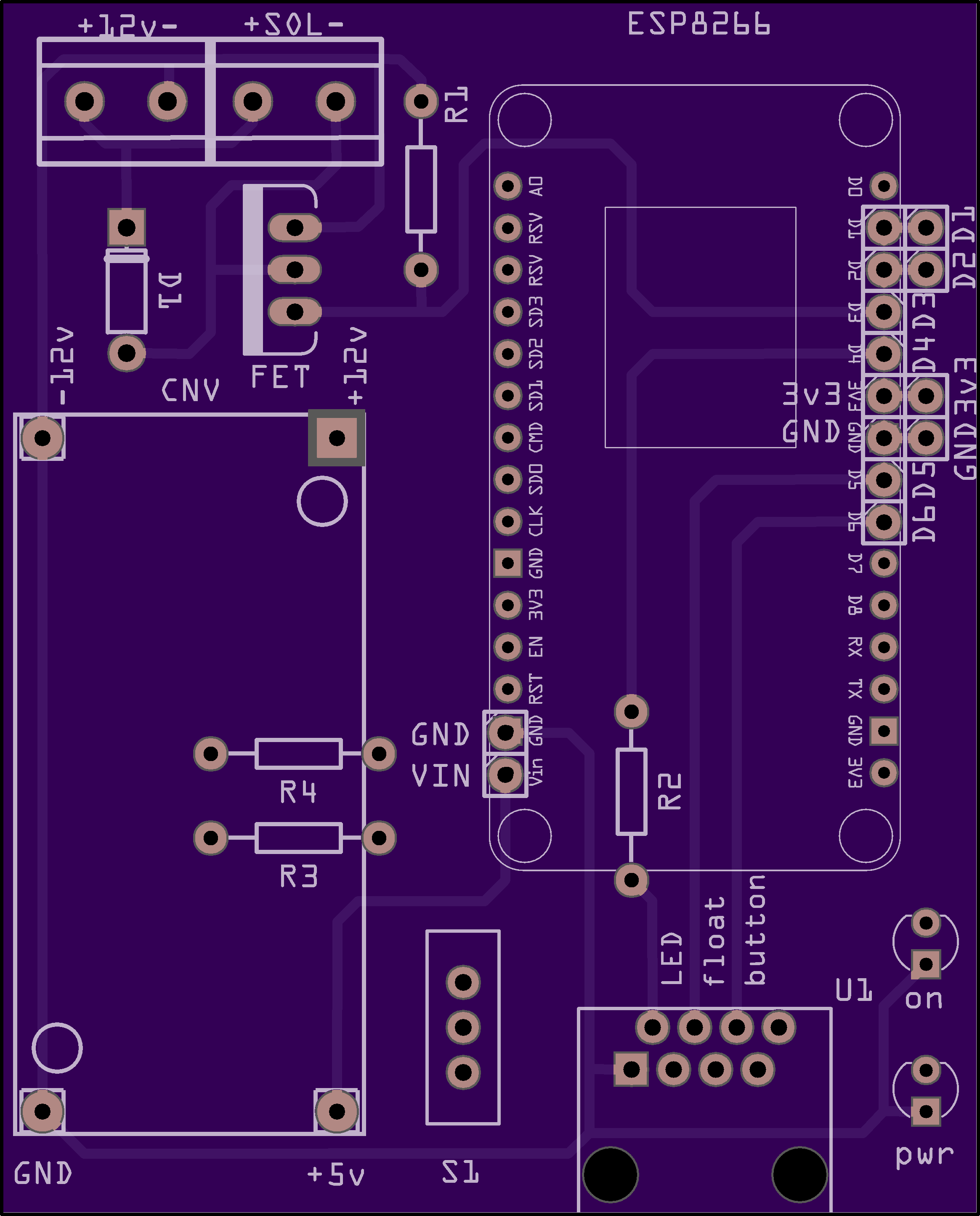
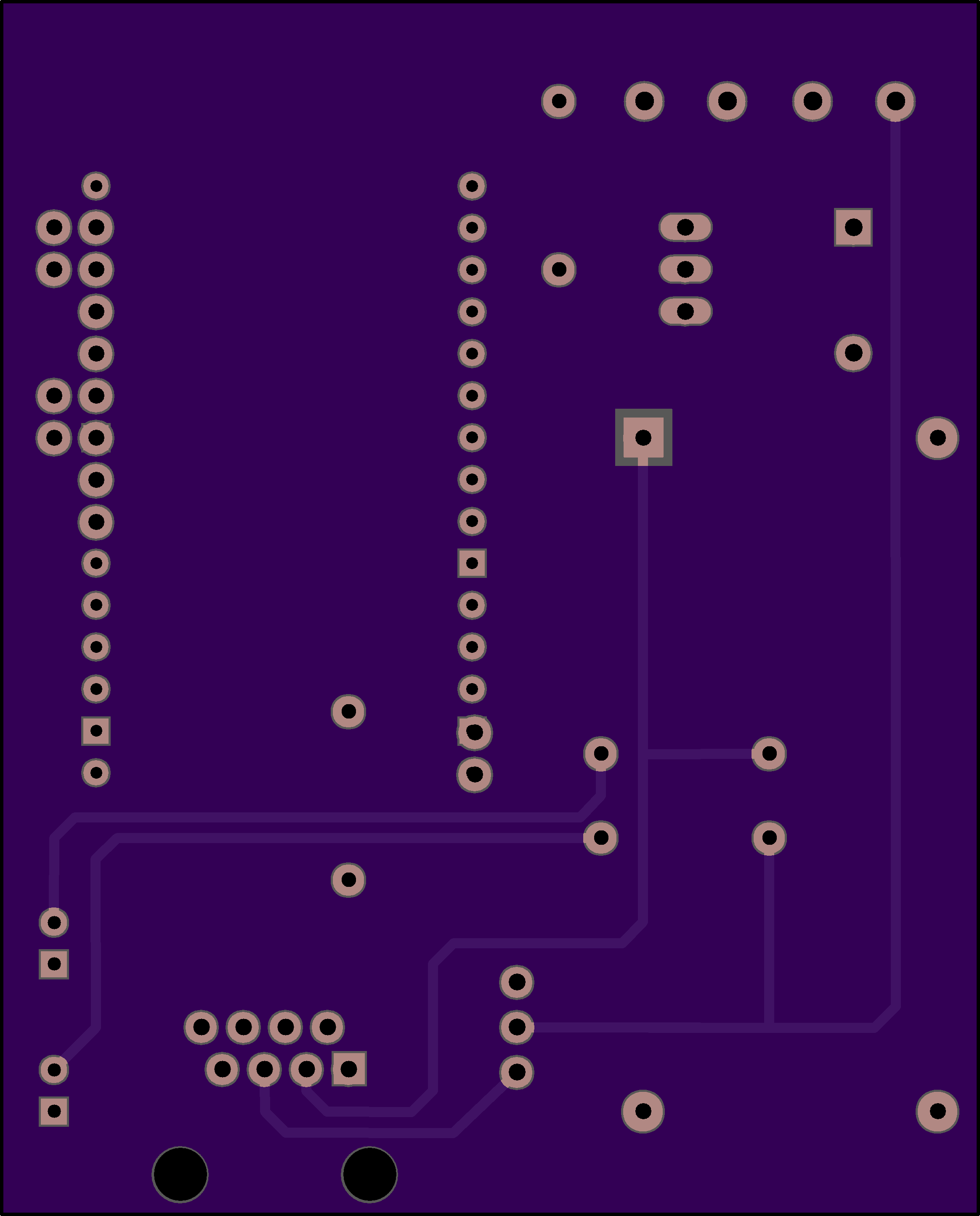
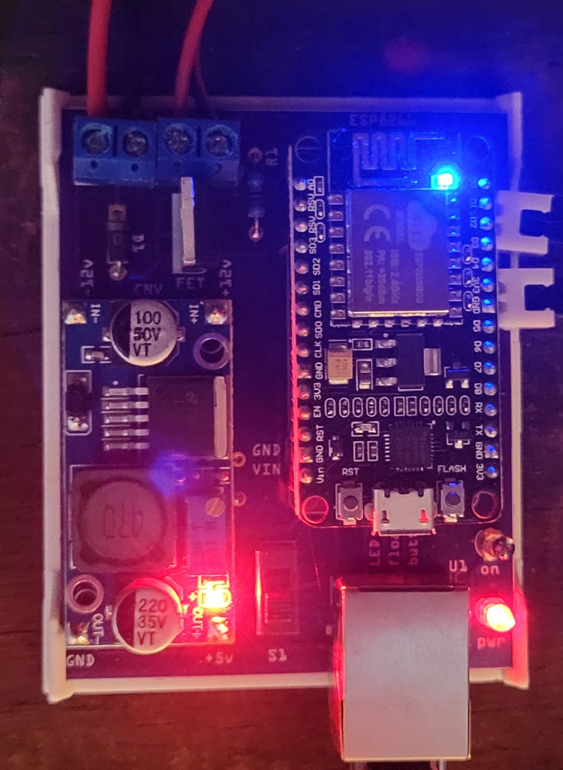
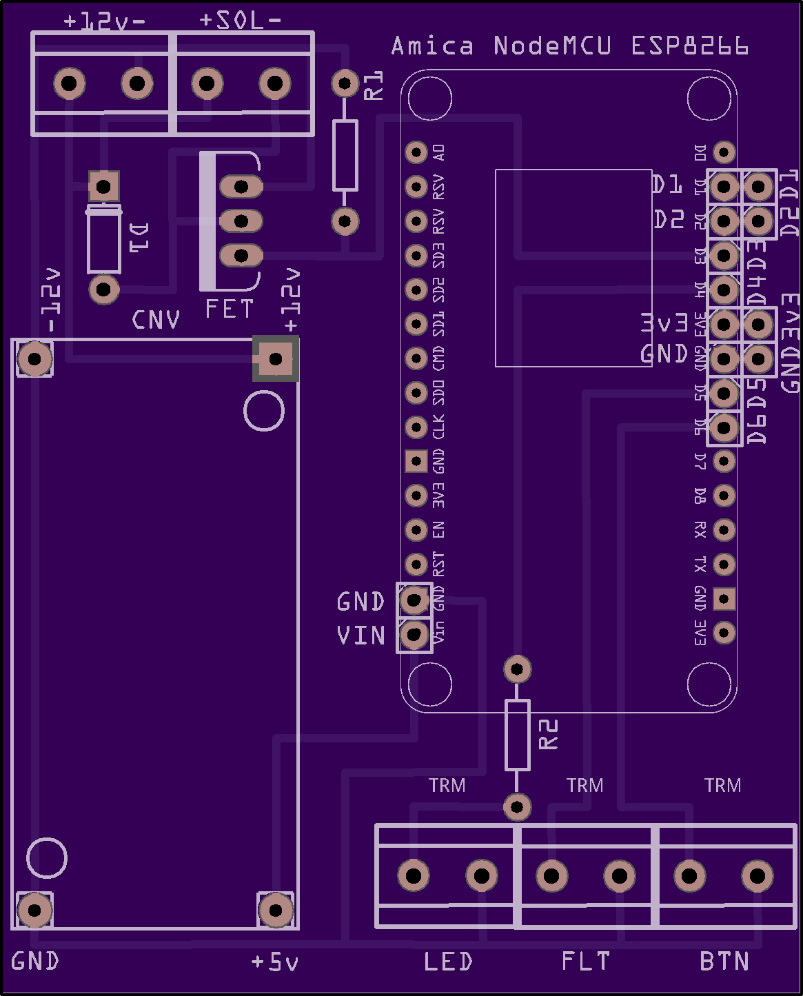
- A custom circuit board that holds an ESP32 as the “brain” of the operation
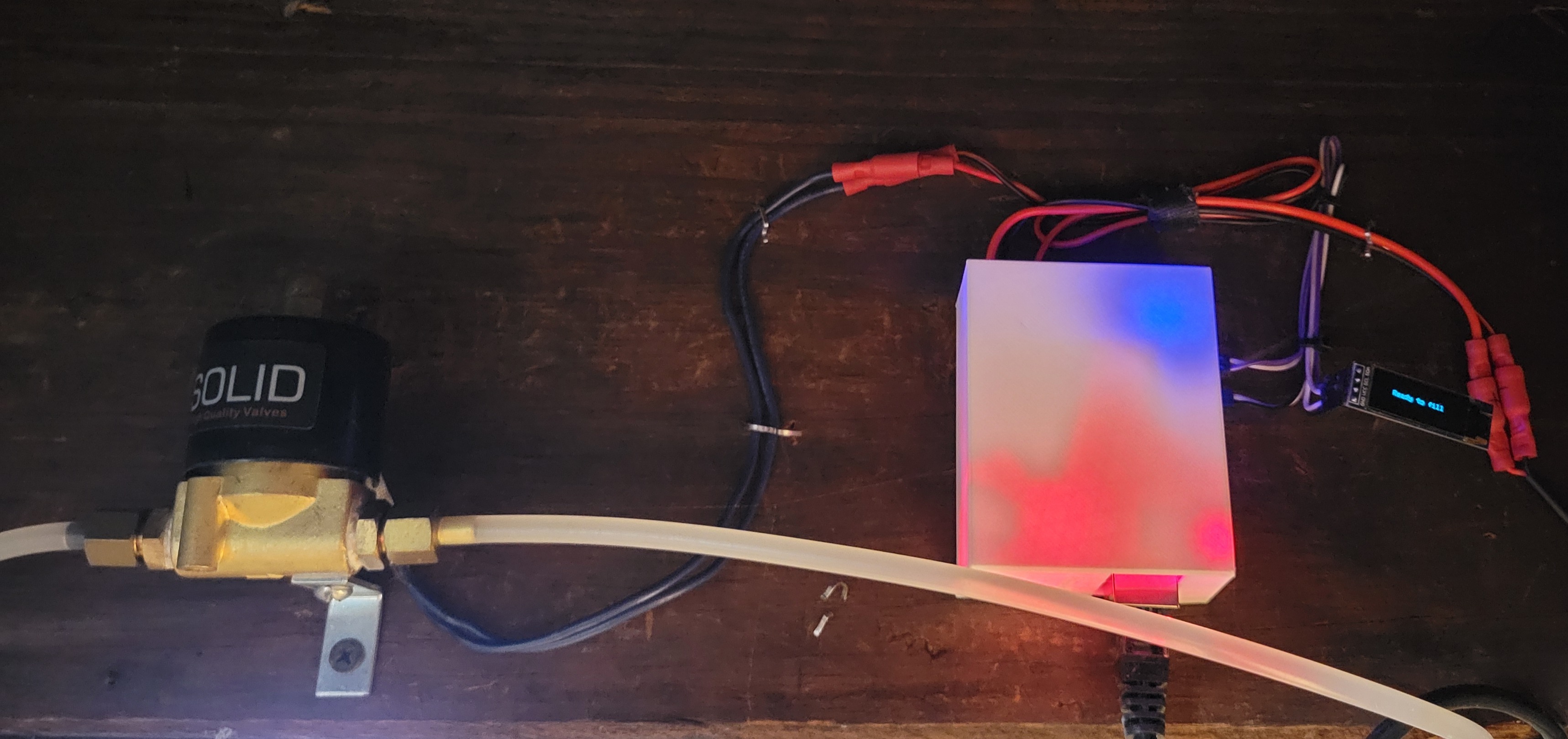
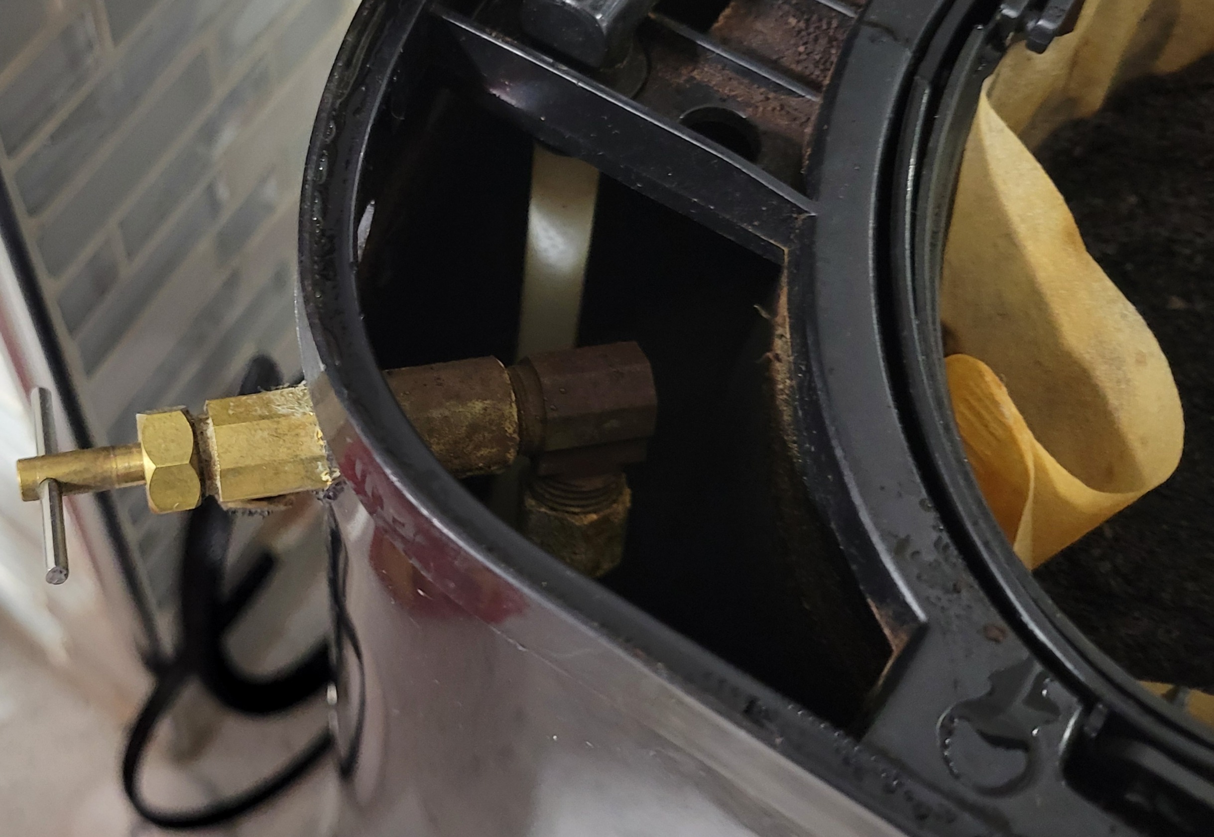
- A solenoid that can open and close a standard 1/4" water line
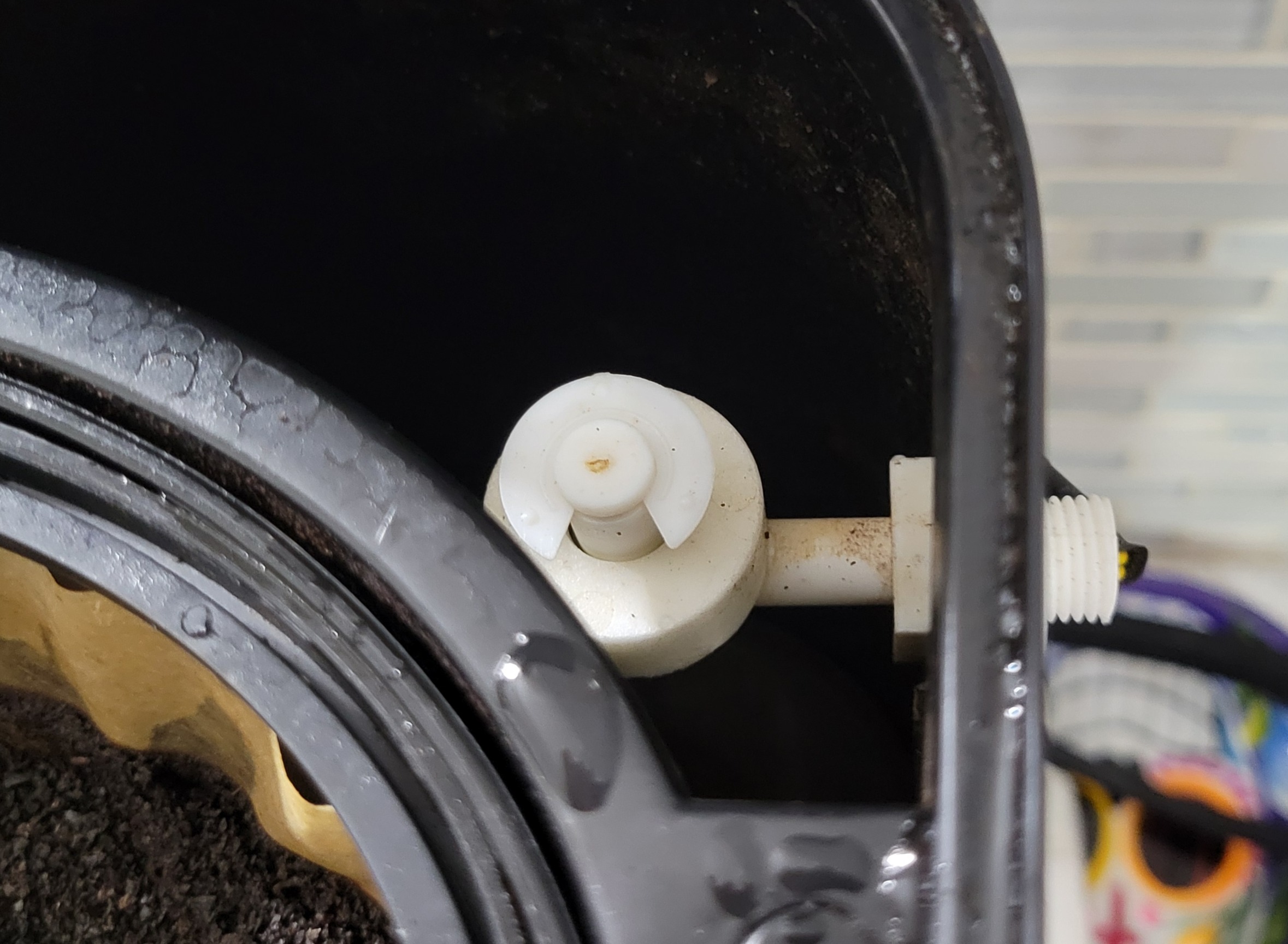
- A float that shorts to ground when the tank is full
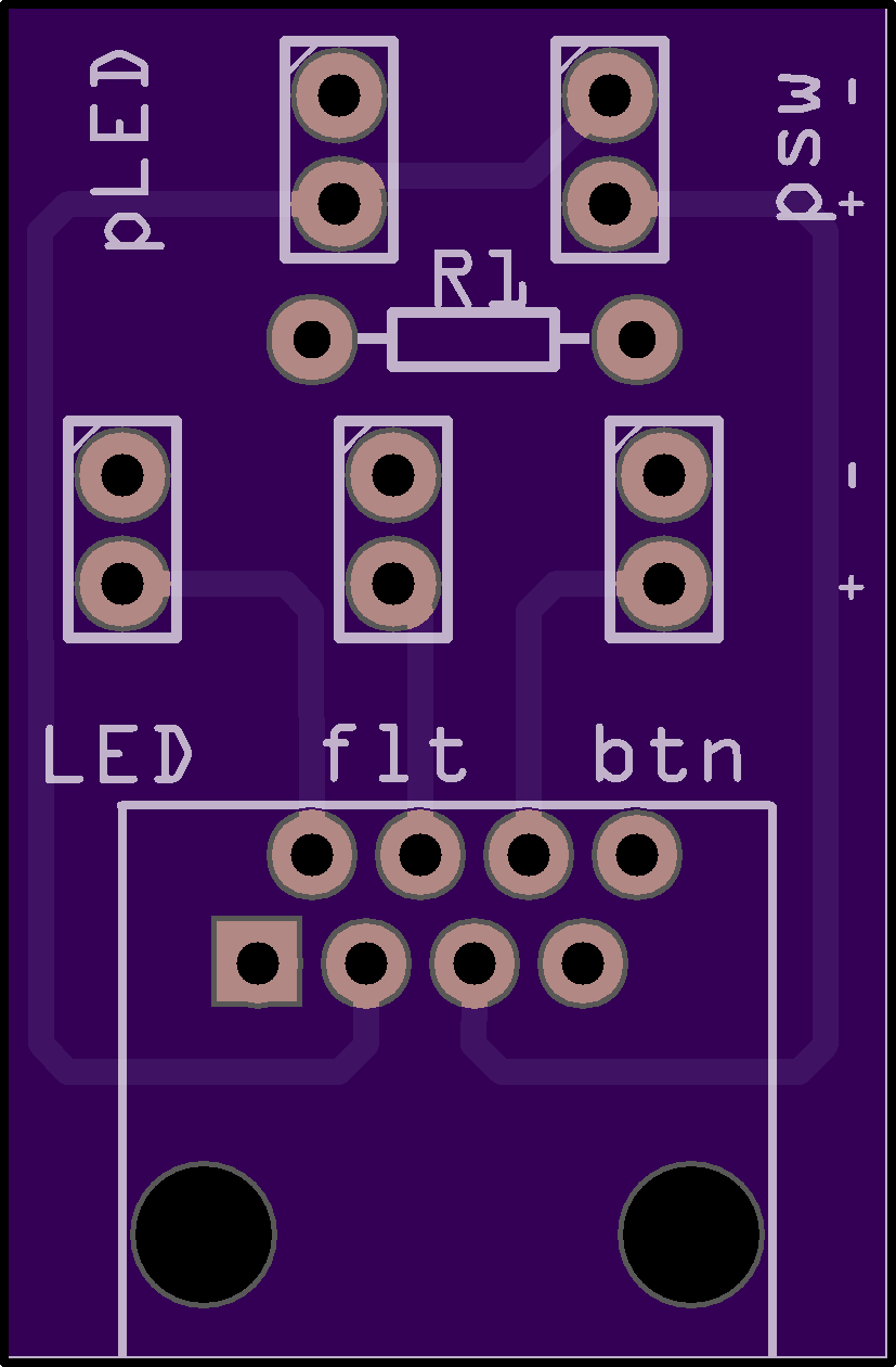
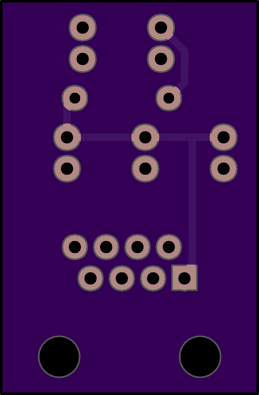
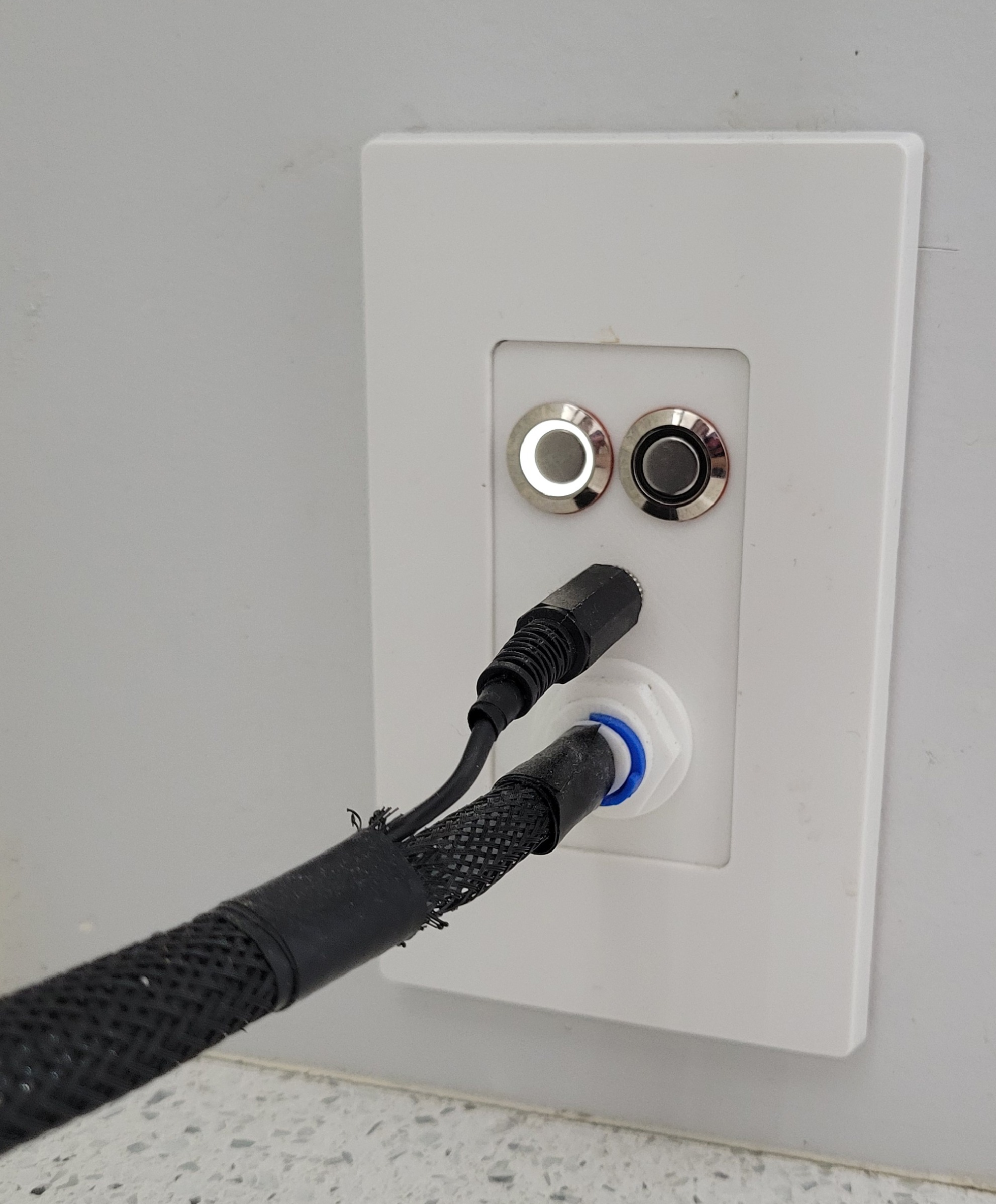
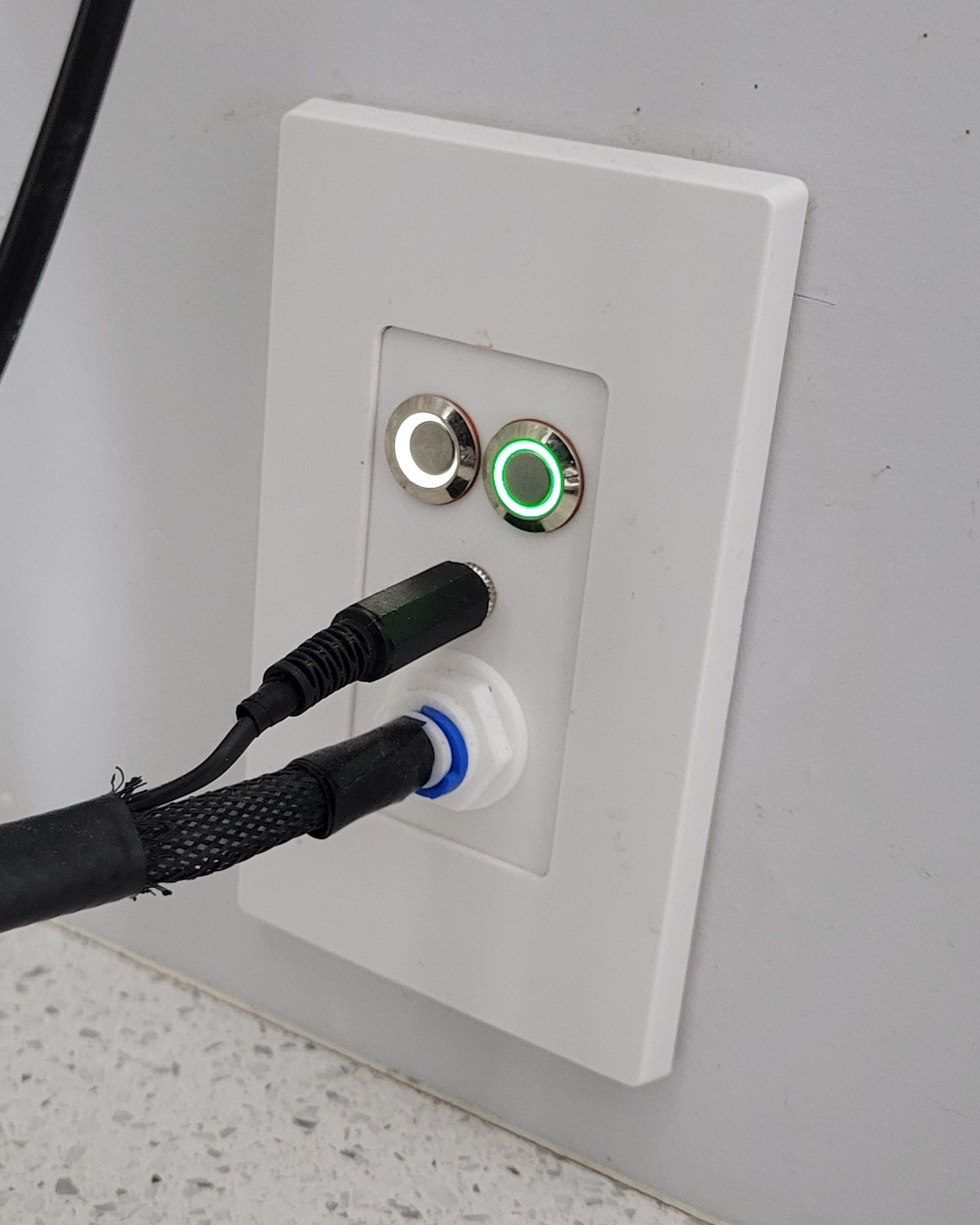
- A wall plate that holds the power button and the “fill the tank” button
The logic is pretty simple. If the float is not shorted and the button is pressed, the solenoid is opened allowing water to start filling the tank and the halo around the button lights up. Once the float is shorted, the solenoid is closed. There is a timeout feature that will close the solenoid in case the float fails as well as a feedback blink of the button if you press it while the tank is already full.
A few unique design facets went into the device. The first of which was defending against the horrors of overfilling. The tank is only so large and the water will keep on coming unless the solenoid is closed. To address this, a few things were implemented. The first, and most visibly obvious one is the float sensor. The float doesn’t serve only for automation, but is positioned in a way that gravity will pull it “closed” and only the buoyancy of the float against water will pull it open. I decided to install it upside down because gravity, as it turns out… is always on. Short of something lodging or preventing the float from moving, it will default to “empty” tank. This may seem backwards, but this design intentionally takes advantage of that first caveat: if something is preventing the float from moving, it would stay in the “full” position after the coffee runs. This will mean that a press to the activation button will do nothing but provide a visual indicator that the tank is already full.
The other way to combat overfilling lies in the software itself. There is a timeout that starts when the solenoid opens and, after having filled the tank a number of times, I determined that if the tank isn’t full in a bit more than 60 seconds, something isn’t right. The timeout will close the solenoid in that case, regardless of what the float reads. There was also some intentional thought into choosing the solenoid itself - it is a NC (Normally Closed) solenoid, so unless the board is providing power to open, it will not. This prevents accidents such as losing power during filling causing an overflowing tank as well as cases if the board releases the magic smoke (to an extent).
V2 Improvements
This is the second design of the coffeenator board, believe it or not.
Split the board

The original design placed the board and all the guts in the wall cavity just behind the face plate. This worked fine, of course, but it was a pain in the backside if I needed to perform maintenance on the board. The turning point for needing a new design was when the timeout would sometimes trip by error - I guess because sometimes the water pressure is lower than others, and sometimes the fittings can get clogged with sediment or whatever. I needed to increase the timeout, but the whole idea of needing to disassemble the wall plate and pull everything out was choresome.
To fix this, I decided to redesign how everything connects up. Rather than messing about with having to disassemble the wall faceplate, I decided to split the interface and the main board. This way, I could place the main board in an accessible location (in the basement) and run a wire to the interface that allows connections. When I need to flash the board with a new ROM, I could just go downstairs and grab it off of the wall.
Get rid of the screen
OK, I’m known for being a bit extra… and to put that in practice, the original coffeenator had a small OLED screen about an inch wide above the buttons to provide feedback to the user. It served as a status screen with messages like “ready to fill” and “tank full”. This turned out to be… neat, but not very useful. Because of how the code was designed, you could press the fill button as many times as you want and action will only be taken if the tank is ready to fill. The simple “blink” feedback to the user around the fill button is enough to let me know that the tank is already full. Plus, let’s be real. This thing sits about five inches away from the tank - I can already *see* if the tank is full or not anyway.
The original coffeenator went live in 2021 and, after a year or two of service, the screen stopped working. This fact served as another reason to make maintenance easier. As it turned out, the screen was just fine… but had come loose from the connectors on the board since they were attached only with DuPont pins (D2 and D1 as well as GND and 3v3 on the right of the board). This wasn’t very secure at all and through some force of nature in the wall, they eventually worked loose.
As part of the redesign to split the board and the interface, I decided that messing with the screen just isn’t worth it. The cat5 connector does have four unpopulated pins which should allow me to run the I2C (Inter-Integrated Circuit) connection over the cable, but I have first-hand experience that running I2C communications for an OLED screen over cable is terribly unreliable. With the fact that the screen doesn’t DO much and that I may need to spend more time dorking around with getting it working over a cable, it was easy to just remove it from the equation. This also served as a nice enough reason to redesign the faceplate to fit in the opening of the Decora plate just a bit better, too! This is because the original design was maybe about 1/2mm too big, and fit poorly.